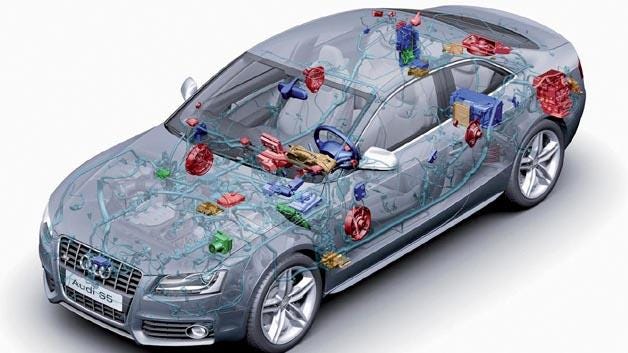
Electronic communication has played such a significance that electronic comprises of 70 percent of systems in vehicles. The remaining 30 percent is mechanical components. Almost all safety relevant systems communicate via CAN or Flexray Bus. Our vehicle that we drive with approximatly 150 ECUs have already made thousands, tens of thousands decisions for us by collecting tens of thousands of signals from various sensors.
When we try driving a very old vehicle ( like a model produced in 1980s) and another vehicle produced in 2019 and compare the two driving experiences, we are baffled by how people could drive these “really old” vehicles, and realize how little effort we put into “driving” a vehicle (Who knows how you will feel after seeing the 100% self driving automobiles on the street and that the driving licenses you obtained many years ago do not have any value?)
My special advice is to place cones on a straight line at regular intervals and try slaloming in between the cones at different speeds with both vehicles. 🙂 This will underline the importance of the saying “ Tool works, hand becomes proud of it.” Unfortunately, personally witnessed this during the test track of Bosch in Boxberg!
It is also vital to state that it is necessary to put extra effort into having an accident while driving a semi autonomous car: lane tracking, collision avoidance system, an adaptive cruise control system determining speed of the vehicle based on the vehicle in front rather than the driver (self acceleration and braking), automatic parking system (self parking), a 360° angled camera, a head up display, speed limit support, adaptive front-lighting system, esp, eps, abs…
It is possible to see how the dynamic driving system I worked on for the four years impacts driving experience in the following example.
Network communication underlies all of this vast data transfer and decision making process. Totally different systems bring different requirements having different complexities and safety levels (ASIL) as well. For Example; the breakdown of which system will impact your driving: the steering wheel or air conditioner? Or do you want your ABS or in vehicle lighting system be processed in a short time?
For this reason, vehicle network communication has led to arousal of many communication protocols such as CAN, Flexray, and LIN depending on the importance of each system in the vehicle, its location ( cable length will vary) and cost.
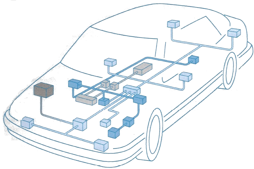
We can think of vehicle network as a system which consists of many smart products making decisions ( (ABS*, ESP*, EPS*, etc.) and their ECUs coming together forming groups as well as sharing data. This system also has a constant flow of data. In the vehicle network we show each element in this system as the node point and the communication relationship with a line.
In vehicle network a different network communication protocol is preferred depending each ECU’s needs. You can think of this as people’s conversations with each other with predetermined rules. While LIN works as a teacher giving right to students to talk, CAN as random conversations of people knowing each other in a party without any collisions and Flexray as a conference in which the speech order of a group of presenters are predetermined in detail minute by minute.
In this blog post series, I will mention CAN which is the widely used vehicle network.
Itis really useful to state that if your name is Can, you live abroad, and work in automotive industry, there is no limit for being exposed to jokes making fun of your name especially to the jokes of German people, who are famous for their sense of humor(!)…:)
CAN is the first bus communication protocol which has gone into mass production. It has already become standardized, and it has even been used in various fields from biomedical products to automation technologies. The reason for this is that it has low cost and also that it is reliable. CAN is used in different fields such as motor management, air conditioning, charging systems in hybrid vehicles and electronic power steering. For example, communication in the motor of a vehicle requires being faster than communication in comfort. Therefore, CAN network communication is integrated by different data transfer speed.
It is possible to mention two kinds of CAN communication network depending on data transmission speed:
The main properties are as follows:
The first byte defines the length of consecutive data (For example, 0x02 = 2 Bytes, 0x07 = 7 Bytes) and the remaining bytes are reserved for the data sent or received. If CAN message is composed of a single message, and if the message length is equal to or smaller than 8 bytes, it is a “Single Frame”.
E.g. 03 2E 06 00 (A UDS message “Write Coding Value”)

If our received CAN message is longer than 8 bytes, it is received as “The first Frame + Consecutive Frame”. The first part of this message format includes the first frame. In the first byte “0x1″ represents “First Frame”, the remaining bytes in byte 0 and byte 1 are divided into message length. 6 bytes of space remains in the first message. The remaining data are read as consecutive messages.

Message(s) received after the first message and flow control message are named “Consecutive Frame”.

Just like in the first message, we can see an “0x2″ which represents a consecutive message in the first byte. “n” represents the order of the consecutive messages not the length of data length; it acts as an index ( like (0x21, 0x22, 0x23,… )
An example to a single, first, flow control and consecutive frames:
03 22 06 00 (Received Message — Single)
10 0A 62 06 00 00 30 22 (Response message sent — The first message, you can see that the data length equals to 10 Baytes (Hex 0x0A) in the message)
30 00 00 (Flow Control Message)
21 7E FF 02 00: As the message does not fit into one single message, the consecutive message was sent right after the first message. Since the remaining message is only 4 bytes, one single consecutive message is enough in this situation.
It is the message controlling the flow of consecutive messages; it determines the amount and frequency of consecutive messages.

Protocol Control Information (PCI) consists of three bytes:
Byte #0: In the high byte (HB), we can see “0x3” which represents the flow control message. In addition, in the low byte (LB) “S” specifies the flow status of consecutive messages. It can take three values:
0 = ClearToSend, 1 = Wait , 2 = Overflow
Byte#1: It is reserved for the block size which determines the allowed number of consecutive message. (BS: Block Size)
If BS = 0, consecutive messages are sent regardless of any limitations.
Byte#2: It is the minimum wait time between two consecutive CAN messages. (STMin: Minimum Separation Time)
Example: S = 0, BS = 5, STMin = 20 ms
0x30 05 14
I am leaving you with a read error memory message and its answer:
In short, ECU receives the 03 19 02 0C message and ECU answers it with 59 (Positive Response) 02+ data in response.
03 19 02 0C (The request message which is delivered to ECU)
10 4B 59 02 FF E1 14 20 (ECU’s response message starts: First Frame)
30 00 00 (Flow Control Message: S= 0, BS = 0, STMin = 0)
21 2F 55 60 70 2F 50 00 (Consecutive Message 1)
22 03 1F 20 30 21 2F 50 (Consecutive Message 2)
23 00 02 5A 39 34 22 2F (Consecutive Message 3)
24 13 43 00 13 14 00 0E (Consecutive Message 4)
25 7E A9 40 09 31 D2 20 (Consecutive Message 5)
26 7F 12 23 A3 12 24 AA(Consecutive Message 6)
27 20 07 28 A0 01 01 14 (Consecutive Message 7)
28 11 24 AA 22 E0 24 9C (Consecutive Message 8)
29 28 99 01 00 11 1F 1F (Consecutive Frame 9)
2A 00 2F DD 25 00 2F (Consecutive Frame 10)
Translation from original text: Beyza Yilmaz